K-factor table: which value should you use for bending?
In this article, we explain how to choose the K-factor from the DIN 6935 table, what changes with the die, the process and the material, and how to measure your press brake's K.
In this article, we present a K-factor table for bending steel sheet, calculated from the DIN 6935 standard. Below, we explain how to estimate the inside radius, how the process and the material affect K and how to measure your press brake's K with a test piece.
What is the K-factor?
The K-factor gives the position of the neutral axis, the layer whose length does not change in the bend, within the sheet thickness:
K = d ÷ t
where:
- K = K-factor (dimensionless);
- d = distance from the inside surface to the neutral axis (mm);
- t = sheet thickness (mm).
Since the flat pattern is as long as the neutral axis, K sets the size of the blank, as we explain in how the K-factor changes your flat pattern. It is not a material constant: it depends on the radius the bend forms, and that radius depends on the die, the sheet and the process.
K varies mainly with Ri/t, the ratio of inside radius to thickness. On a tight radius, the neutral axis moves inward and K drops; on a large radius, it moves back toward mid-thickness and K approaches 0.5 (Figure 1).
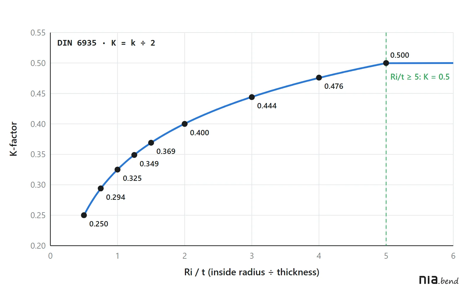
K-factor table from DIN 6935
DIN 6935, the German standard for cold bending of flat steel products, gives a correction factor k for the position of the neutral axis:
k = 0.65 + 0.5 × log10(Ri/t), for Ri/t below 5
k = 1, for Ri/t of 5 and above
where:
- k = DIN 6935 correction factor (dimensionless);
- Ri = inside radius of the bend (mm).
In the standard, the neutral axis sits k × t/2 from the inside surface. The K-factor, the fraction of thickness that CAD programs ask for, is half of that:
K = k ÷ 2
| Ri/t | k (DIN 6935) | K = k ÷ 2 |
|---|---|---|
| 0.5 | 0.4995 | 0.250 |
| 0.75 | 0.5875 | 0.294 |
| 1.0 | 0.6500 | 0.325 |
| 1.25 | 0.6985 | 0.349 |
| 1.5 | 0.7380 | 0.369 |
| 2.0 | 0.8005 | 0.400 |
| 3.0 | 0.8886 | 0.444 |
| 4.0 | 0.9510 | 0.476 |
| 5 or more | 1.0000 | 0.500 |
Three caveats: the standard was written for steel; the Ri in the formula is the radius the press brake forms, not the one on the drawing; and the table is only a starting point.
Estimating the inside radius from the die
In air bending, the radius comes from the die opening (V), and two rules of thumb help you estimate it:
V = 8 × t
V ÷ 8 ≤ Ri ≤ V ÷ 6
where:
- V = die opening (mm).
A V of 8 × t is the most quoted; thin sheet often goes in a V closer to 6 × t and heavy plate in 10 × t or more. The radius range holds, roughly, for mild steel. Stainless forms a larger radius in the same V (a common reference for 304 stainless is around 20% of V); in aluminum, the result varies a lot with alloy and temper.
NiaBend's die selection shows the ideal opening range for the part (Figure 2).

Example: 2 mm mild steel in a 16 mm V (8 × 2). The radius lands between 16 ÷ 8 = 2.0 mm and 16 ÷ 6 = 2.67 mm, so Ri/t is between 1.0 and 1.33. From the formula, K is between 0.325 and 0.356; in practice, between 0.33 and 0.36. In NiaBend, with the 80° punch, that 16 mm V and SAE 1020 steel, the bends get a 2.67 mm radius (Figure 3).
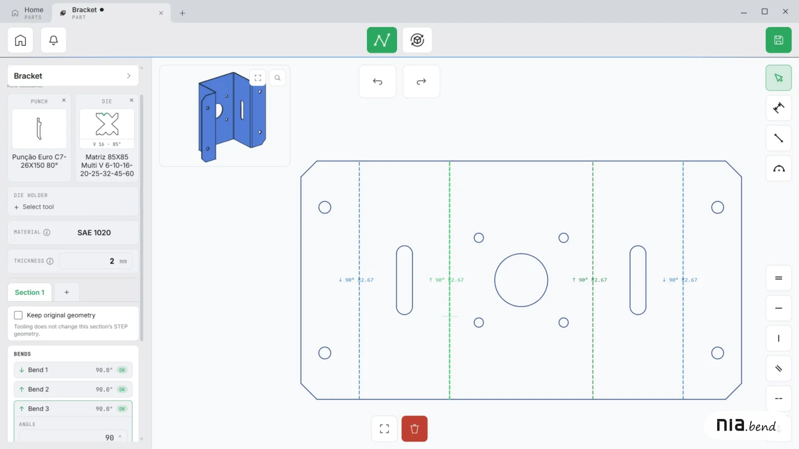
The process changes the radius, and K with it
The process changes K because it changes the radius and, in coining, the thickness too:
- Air bending: the sheet touches only the punch tip and the die shoulders. The radius comes from the V and the material, and springback is the largest of the three.
- Bottoming: the sheet is pressed against the die walls. The radius gets closer to the punch tip radius, springback drops and tonnage goes up.
- Coining: the punch tip penetrates and thins the sheet at the bend. The radius follows the punch, springback nearly disappears and tonnage is several times higher. Since the thickness is no longer nominal, the table loses accuracy.
The effect of the material
At the same Ri/t, the difference in K between mild steel, stainless and aluminum is usually smaller than the effect of Ri/t itself. Material matters more through the radius that forms in the same V and through springback.
Austenitic stainless work-hardens more than mild steel, with a higher strain-hardening exponent (n), and forms a larger radius in the same V. In NiaBend, n is the material property that changes the calculated inside radius the most (Figure 4). Aluminum, for its part, has an elastic modulus around 70 GPa, against about 200 GPa for steel, and that weighs on springback.

How to measure your K with a test piece
Your process's K comes from working backward from a part bent on your own press brake:
- Cut a strip from the same batch of sheet and, after cutting, measure its actual length and its thickness (with a micrometer): L = 200.00 mm and t = 2.00 mm.
- Bend it to 90° with the production punch and die, here a 16 mm V. If the angle isn't 90°, adjust and bend another strip.
- Measure both flanges on the outside, to the outside apex, and the inside radius with a radius gauge: A = 102.10 mm, B = 101.76 mm and Ri = 2.6 mm.
- Calculate the bend deduction, BD = A + B − L = 3.86 mm, and the bend allowance, which at 90° is BA = 2 × (Ri + t) − BD = 9.2 − 3.86 = 5.34 mm.
- Calculate K, with φ = 1.5708 rad at 90°: K = (BA ÷ φ − Ri) ÷ t = (3.3995 − 2.6) ÷ 2.0 ≈ 0.40.
From the DIN 6935 formula, with Ri/t = 2.6 ÷ 2.0 = 1.3, K would be 0.353 and the bend deduction 4.01 mm, against the 3.86 mm you measured: 0.15 mm per bend, almost 0.6 mm on a four-bend profile. In this case, the measured K, 0.40, is the one to use.
The math is sensitive to measurement: a 0.1 mm error in A + B shifts K by 0.1 ÷ (1.5708 × 2) = 0.032, so bend three strips and average them. The 3.86 mm applies directly to 90° bends with that combination; K, together with the Ri used in the calculation, carries the result to other angles, but it holds best near 90°, since more open bends tend to form a larger radius.
Where your K goes in NiaBend
In NiaBend, each bend's Inner radius and K-factor accept a typed value that overrides the calculated one, and the bend shows the resulting bend allowance and bend deduction as BA and BD. A new part starts in Calculated mode, with the radius coming from the die and the material in your library.
Conclusion
The DIN 6935 K-factor table is a good starting point, as long as the calculation uses the radius your die forms, not the one on the drawing. For the combinations you bend most, measure K with a test piece: a 200 mm strip and a few minutes of measuring are enough.
To use these values in your flat patterns, try the free NiaBend demo.
Frequently asked questions
Which K should I use if I can't run the test now?
Estimate the radius with the die-opening rule, calculate Ri/t and use the table. For mild steel in a V of 8 times the thickness, that gives K between 0.33 and 0.36. Check the first part before cutting the batch.
Do I need a K for every thickness?
For every combination of thickness, die and material, Ri/t changes, and K changes with it. Your own table, with one row per combination you use, takes care of it.