Press brake simulation: what are the benefits in production?
In this article, we explain what a press brake simulator changes in production for the operator, the setup person and process engineering, and what it does not replace.
In this article, we explain the benefits of a press brake simulator in sheet metal production. Below, we cover what simulation changes for the operator, the setup person and process engineering, and what it does not replace.
What is a press brake simulator?
A press brake simulator is software that reproduces the bending of a part on screen, with the machine, the tooling and the sheet on file. It moves the trial done at the press brake to the computer: picking the tooling, setting up, trying a bend order and finding out whether a flange hits the ram.
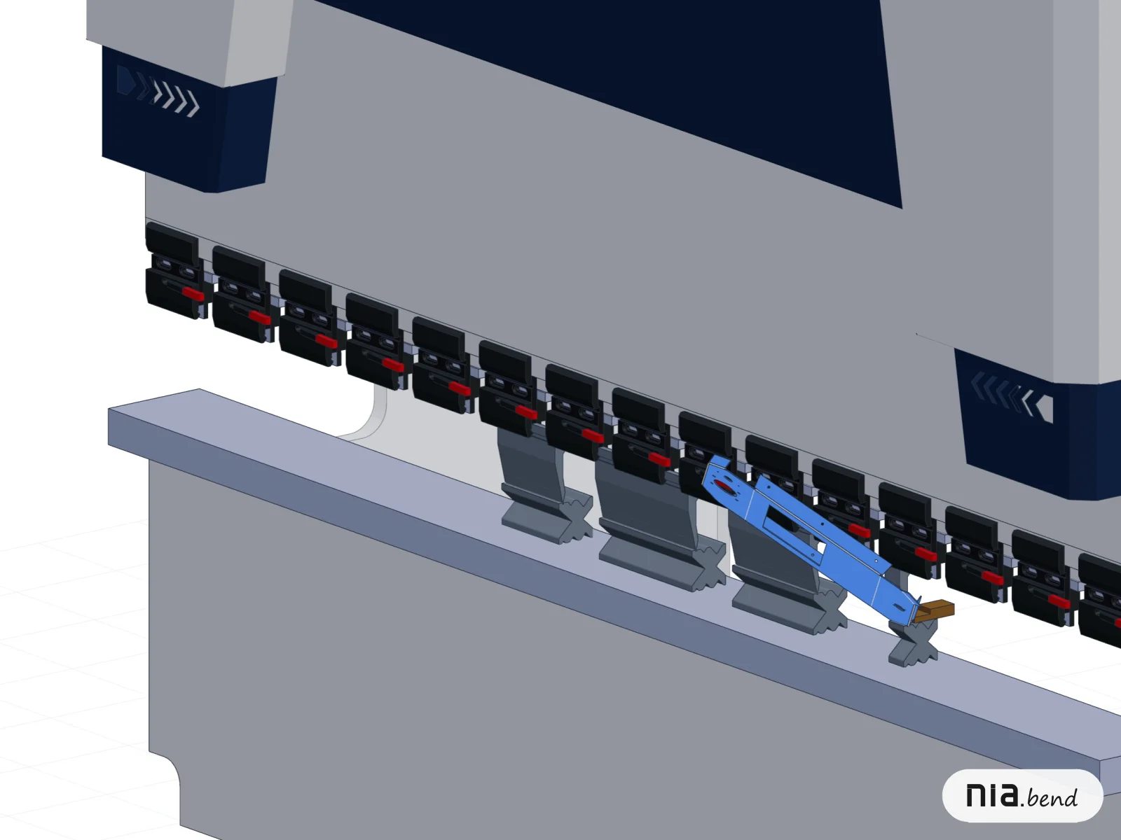
That trial takes up the time between getting the drawing and making the first good part, a cost that never shows up on the quote. Figure 1 shows an example of a 3D simulation in NiaBend.
Fewer test parts
A test part costs material, machine time and operator time. When the blank came off the laser, that material is gone for good.
Simulation does not eliminate the first part, which is still checked bend by bend. What changes is the road to it. The bend order, the tooling and the axis positions arrive already decided and checked, and what is left is fine-tuning the angle. The correction entered on a bend is also saved with the part, for that machine.
Collisions caught before the machine
At the press brake, a collision usually shows up with the part half done, on the third or fourth bend. Some typical cases:
- the flange that swings up into the ram;
- the backgauge that moves in against a part that is already bent;
- the long part that hangs off the bed and hits the floor.
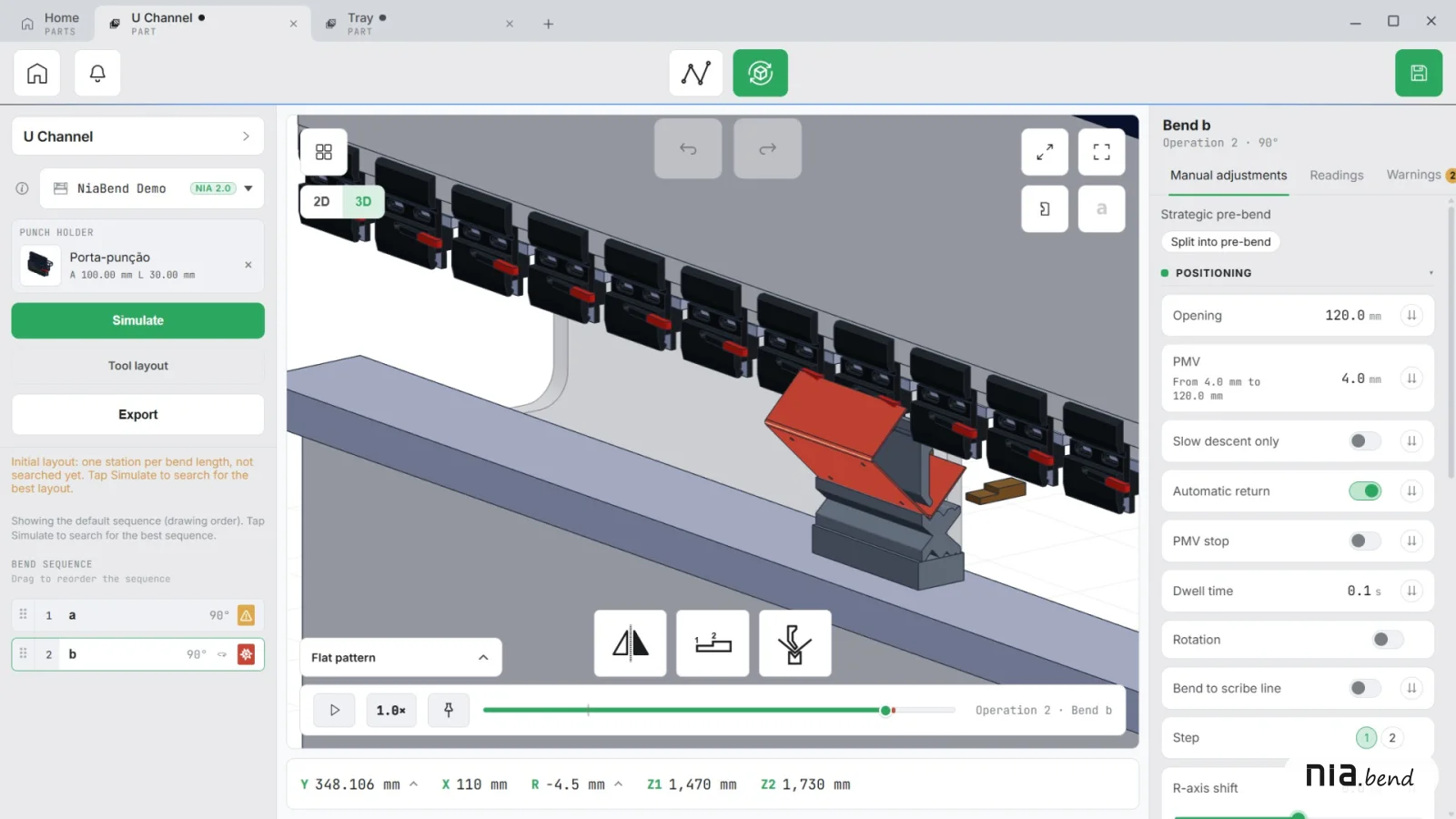
In NiaBend's simulation, the part is checked through the whole stroke against the punch, die, die holder, punch holder, ram and bed, side frame throat, backgauge fingers and floor. Anything that hits turns red, as in Figure 2, and anything that comes too close, inside a safety clearance you set, turns amber. The animation timeline marks where each problem happens.
The check depends on accurate machine and tooling data. That is why, in NiaBend, the machine goes in as it really is. The ram, bed, throat and punch holder are drawn or imported from STEP and checked like any machine drawing, and covers and brackets come in as STEP components in the 3D scene. A tool entered with the wrong working height can pass cleanly in the simulation and crash on the machine.
Simulation is a prediction. It works from the part geometry, the tooling on file and the machine parameters, and it does not replace checking the first part on the machine.
Bend order search
On a part with many bends, one bend done too early can make the next one impossible. The Simulate button evaluates the possible orders and keeps the best one for that machine. Up to 32 bends per section, the search is exact; beyond that, it ranks the orders and warns you. A time limit also applies, and when it runs out, the best attempt so far is kept.
The search works like this:
- the first order it tries keeps the part lying on the die, with the heavy side supported;
- when the backgauge cannot reach the sheet, the part is turned around to gauge off another flange;
- if it still cannot reach, the bend is marked as a bend to scribe line, and the operator positions the sheet by the mark;
- when no order comes out clean, the software says so and shows the one with the lightest collision.
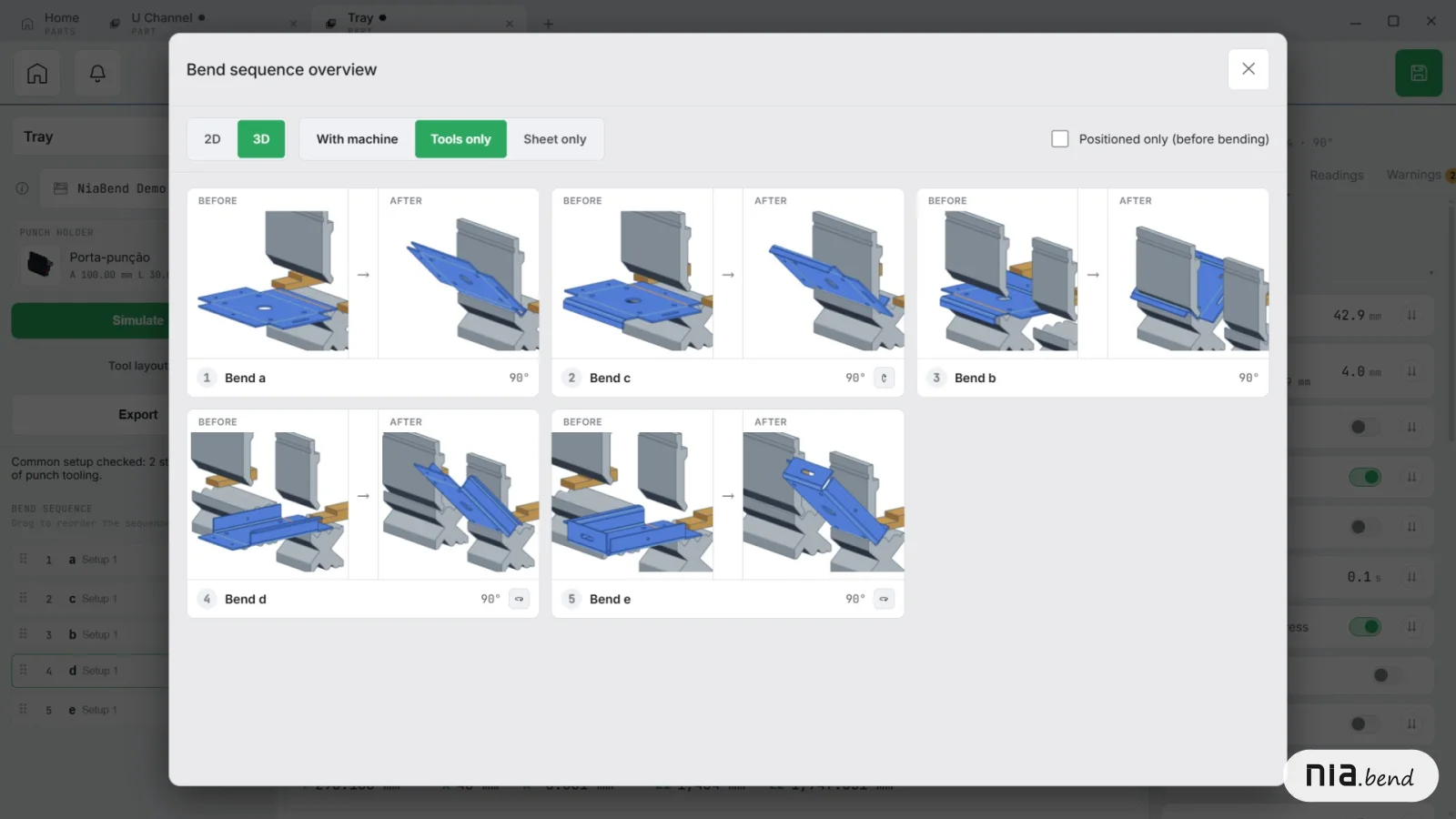
Video 1 shows this search in NiaBend. Once the order is set, the Sequence overview in Figure 3 shows each bend before and after, with the tooling, on one screen.
Some parts need a process bend or a strategic pre-bend, which go into the sequence as steps of their own. The article on pre-bends and process bends explains the difference.
Tooling setup planned in advance
Sectioned punches and dies are common, and the right mix of segments depends on the length of each bend. With each tool's section stock on file, the software builds the row and checks that it covers the bend. On a new part, the tooling opens already set up, with one station per bend length and the longest in the middle of the machine.
The search also sets the stations and where the sheet sits on each bend. When one setup cannot handle the whole part, the work can be split into Setup 1 and Setup 2, with the part unloaded before the changeover. The setup person gets the layout drawn on the machine's scale, in millimeters, instead of working it out by trial.
The process on the operator's screen
Next to the machine, the simulated part opens on the Auxiliary Panel. It shows each bend animated in 2D or 3D, the tooling arrangement and a cue to rotate or flip the part between bends. The operator follows the sequence one bend at a time instead of decoding an assembly drawing.
With no screen at the machine, the bend sequence report comes out as a PDF for printing or as HTML with the animation, which opens in any browser with nothing to install. The HTML file records the checksum of the program generated with it. At the machine, this lets you check whether the paper describes the program loaded in the control.
Production control
With production turned on, the office releases jobs with the part, the machine and the quantity. The operator taps Start on the production list for their machine, and the part opens on the Auxiliary Panel. They pause with a reason and close the job by entering good parts and scrap.
The office indicators compare actual parts per hour with the simulation's prediction. The exported spreadsheet lists, per job, run hours, stop hours and the predicted and actual time per part. Those numbers come from what the operator reports: the list does not read the machine or count parts on its own.
Process stored with the part
In many shops, the bend order for a tricky part lives in one operator's head, and the part waits when that person goes on vacation. With simulation, that decision becomes a file:
- the part keeps the sequence and adjustments for each machine it was simulated on;
- it carries a copy of the tooling and material used and the corrections entered at the panel;
- calibration measurements stay in the library, by material and tooling.
With the files on a server, the office and the shop floor open the same part.
Where to start
- Enter the machines and tooling you actually have, with measured heights.
- Start by simulating the parts that cause the most trouble today: the ones with many bends, the ones that have already crashed and the ones only one operator knows how to make.
- Check the first part of each against the simulation.
Where the two agree, the process is ready to be repeated by any operator.
Frequently asked questions
Does a press brake simulator eliminate test parts?
It does not eliminate checking the first part, which is still required. It cuts down the attempts that used to come before it: the wrong bend order, tooling that cannot reach and a collision discovered at the machine.
Do I need a CNC press brake to use a simulator?
No. If your CNC control is one of the supported ones, the program comes out ready for it. On an NC press brake, the positions go to the Auxiliary Panel and the report, as we explain in how to turn an NC press brake into a CNC.
Conclusion
A press brake simulator cuts test parts, shows collisions on screen, sets the bend order and setup before the machine and stores the process with the part. If your shop loses time on parts with many bends or on collisions found at the machine, start by simulating those parts. If the problem is depending on a single operator, use simulation to turn the sequence into a file.
Simulation also helps at the quoting stage, as the article on bending simulation for quoting explains. To try it on one of your own parts, the free NiaBend demo lets you draw and simulate the bend on your computer.