K-factor: how it changes your sheet metal flat pattern
In this article, we explain what the K-factor and the neutral axis are, how to calculate the flat pattern of a bent part and how much the K value changes the blank.
In this article, we explain how the K-factor affects the flat pattern of a bent sheet metal part. Below, we cover the K-factor, the neutral axis, the flat pattern formulas and an example with a 2 mm sheet U-channel calculated with two K values.
What is the K-factor?
The K-factor is the ratio between the position of the neutral axis and the sheet thickness, in the bend:
K = d ÷ t
where:
- K = K-factor (dimensionless);
- d = distance from the inside surface to the neutral axis (mm);
- t = sheet thickness (mm).
With K = 0.5, the neutral axis sits at mid-thickness. On a tight radius, K falls below that and, on a radius much larger than the thickness, it approaches 0.5. What changes K the most is Ri/t, the ratio of inside radius to thickness, and reference values are in the K-factor table.
Neutral axis
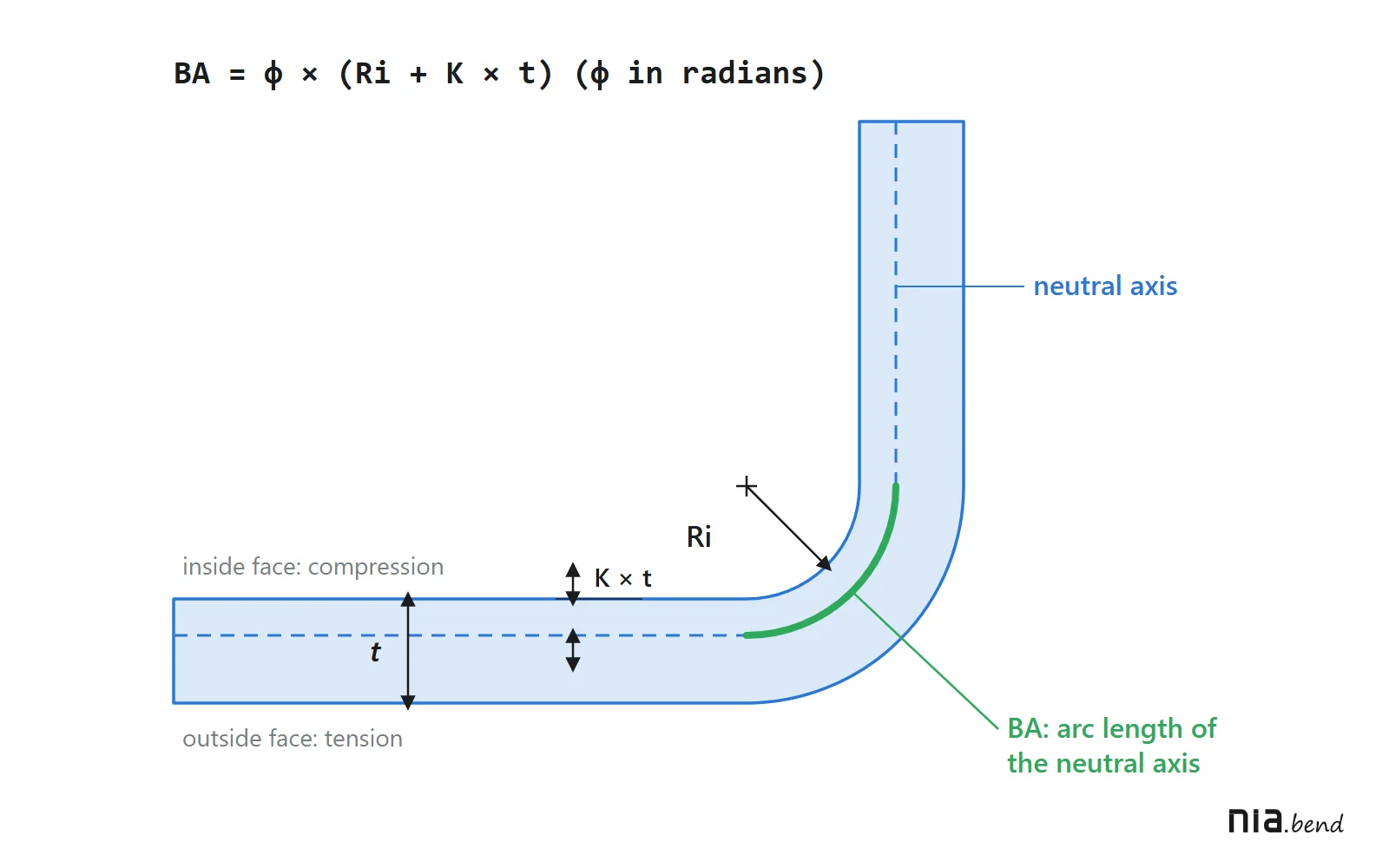
In a bend, the outside of the sheet stretches and the inside is compressed. Between them lies the neutral axis, the layer whose length does not change.
In the flat sections, it sits at mid-thickness; in the bend, it shifts toward the inside, and the tighter the radius relative to the thickness, the bigger the shift (Figure 1).
Flat pattern
The flat pattern, or blank, is the flat sheet cut to the size needed to form the part. Since the neutral axis does not change length, the blank is as long as the neutral axis of the bent part: the flat sections plus one arc per bend.
That is why a wrong K means a wrong blank, and nothing you adjust at the press brake will put back the material that is missing.
Flat pattern formulas
With φ as the angle the sheet turns through in the bend (φ = 180° − included angle), the four formulas are:
BA = φ × (Ri + K × t)
OSSB = (Ri + t) × tan(φ/2)
BD = 2 × OSSB − BA
L = A + B − BD
where:
- BA = bend allowance, the length of the neutral axis through the bend (mm), with φ in radians;
- OSSB = outside setback, from the bend tangent to the outside apex of the flanges (mm);
- BD = bend deduction, what you subtract per bend from the sum of the outside dimensions (mm);
- L = developed length of an L-shaped part (mm);
- A and B = outside dimensions of the flanges, to the outside apex (mm);
- Ri = inside radius (mm), t = thickness (mm) and K = K-factor.
On a 90° bend, φ = 1.5708 rad and OSSB = Ri + t. K only enters the bend allowance, and the bend allowance feeds everything else. In NiaBend, when you open a bend in the list, you see both results, labeled BA and BD (Figure 2).
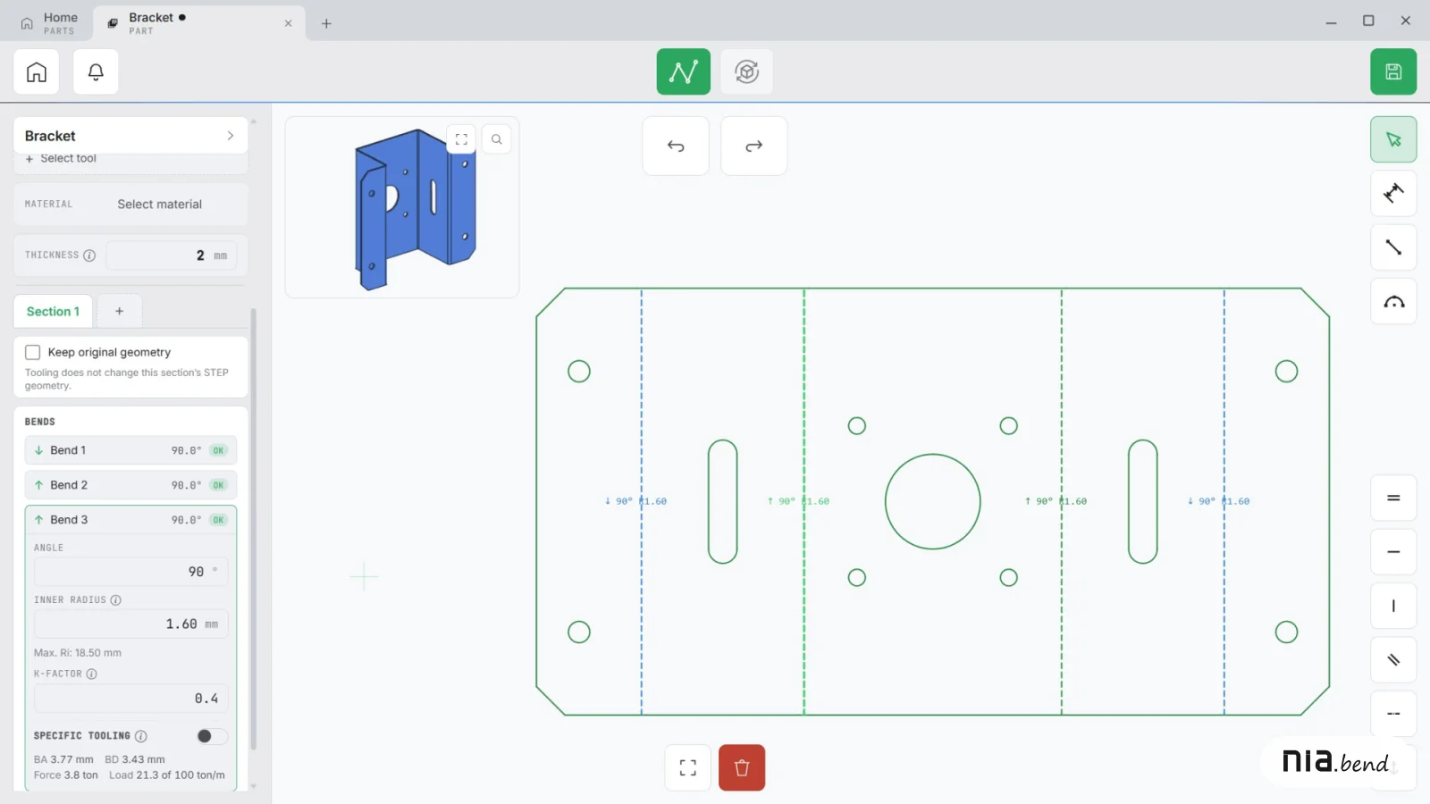
In Figure 2, the 90° bend has an Ri of 1.60 mm and a K of 0.4 on 2 mm sheet: BA = 1.5708 × (1.60 + 0.4 × 2) = 3.77 mm and BD = 2 × (1.60 + 2) − 3.77 = 3.43 mm, as shown on the card.
Example: the same U-channel with two K-factors
Take a U-channel with outside dimensions of 50 × 100 × 50 mm, 2 mm sheet, a 2 mm inside radius and two 90° bends. We'll compare K = 0.33, close to what DIN 6935 gives when the radius equals the thickness (0.325), with K = 0.50, the "neutral axis in the middle" many people use by default. In both cases, OSSB = 2 + 2 = 4 mm.
| Step | K = 0.33 | K = 0.50 |
|---|---|---|
| Ri + K × t | 2.66 mm | 3.00 mm |
| BA = 1.5708 × (Ri + K × t) | 4.178 mm | 4.712 mm |
| BD = 2 × 4 − BA | 3.822 mm | 3.288 mm |
| L = 50 + 100 + 50 − 2 × BD | 192.356 mm | 193.424 mm |
The difference is 1.068 mm, or 0.534 mm per bend. If your process behaves like K = 0.33 and the blank was calculated with 0.50, the sheet arrives 1.07 mm too long. With the backgauge locating both legs at 50 mm, the base takes all of it: about 101.07 mm instead of 100 mm.
The error repeats at every bend, always with the same sign: on a profile with six identical bends, it would be 6 × 0.534 = 3.2 mm. It piles up in the dimension the backgauge does not locate, often the last flange or the base, which is why parts with many bends are the first to expose a poorly chosen K.
Inside radius in air bending
In air bending, the inside radius does not come from the drawing. The sheet touches only the punch tip and the die shoulders, and the radius forms according to the die opening (V) and the material. The punch tip only dictates the radius when it is larger than that natural radius.
For mild steel, a practical reference is:
V ÷ 8 ≤ Ri ≤ V ÷ 6
where:
- Ri = inside radius formed in the bend (mm);
- V = die opening (mm).
For 2 mm sheet in a 16 mm V, that is between 2.0 mm (16 ÷ 8) and 2.7 mm (16 ÷ 6), whatever radius is on the drawing; stainless forms a larger radius in the same V. Since K depends on Ri/t, the flat pattern has to use the radius the press brake will actually form.
K-factor and inside radius in NiaBend
In NiaBend's drawing and flat pattern module, the Ri / K-factor field in the part data has two modes (Figure 3). In Calculated, the default for a new part, each bend's inside radius comes from the selected die and the material properties. In Fixed, the part uses Ri equal to the thickness and K = 0.3. In both modes, an Ri or K typed on a bend still holds.
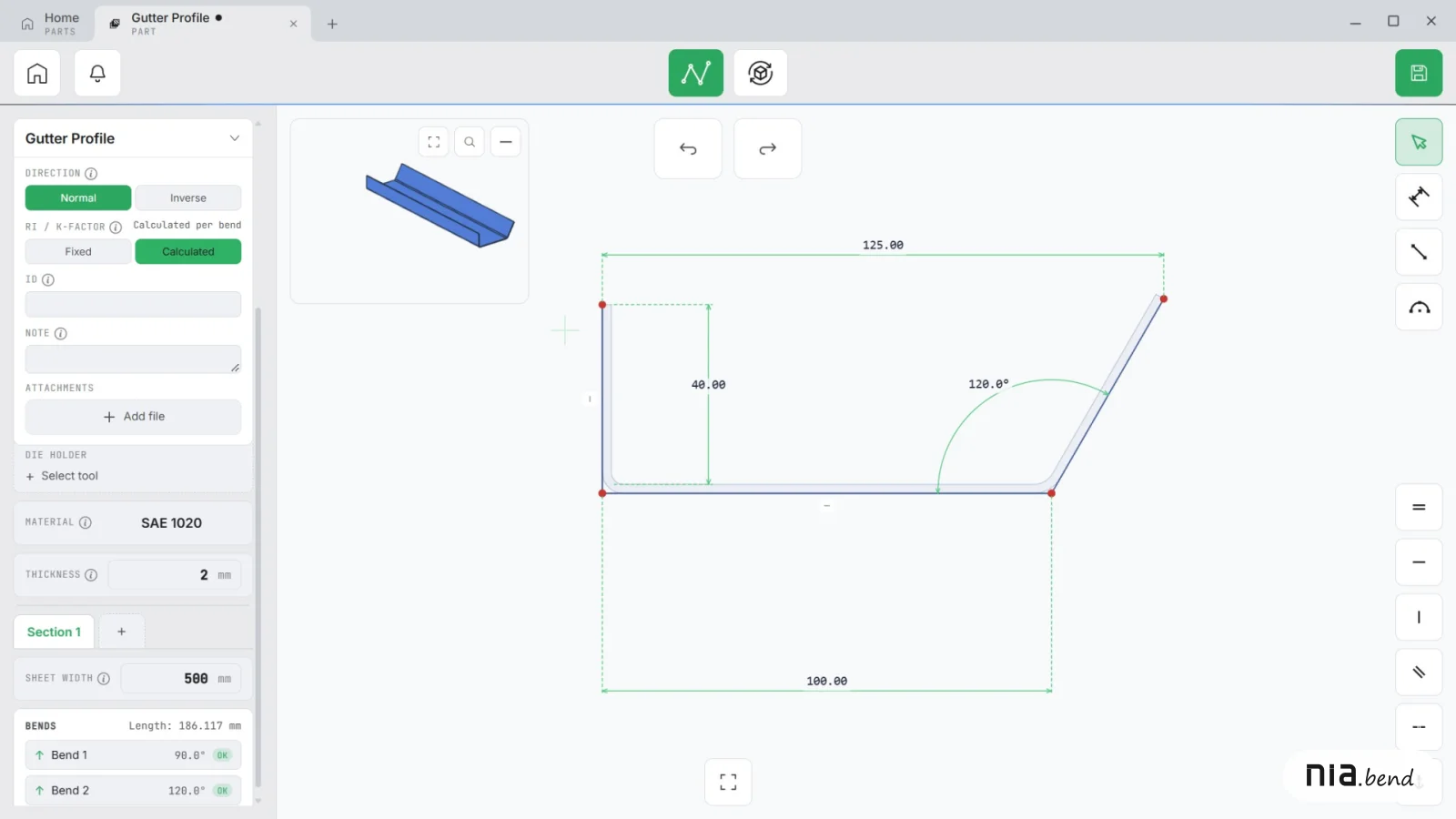
The developed length, next to the Bends heading, is recalculated whenever the thickness, the material or the tooling changes. On a STEP part, the angle, direction and cut outline come from the file, but the inside radius comes from the tooling: the program adapts the part to the radius your die and material will produce, keeps the outside dimensions and starts with K = 0.40 on each bend.
The Compare with the original STEP button, in the enlarged 3D view, shows the part from the file side by side with the adapted part. When the cut outline can't take that radius, the bend row flags it and shows the radius the geometry accepts; if the dimensions are kept anyway, the 3D part marks where the sheet tears or deforms.
The blank preview (Figure 4) is the last check before you export the cutting DXF.

Conclusion
The K-factor sets where the neutral axis lies, and the flat pattern is as long as the neutral axis: on 2 mm sheet, K can decide half a millimeter per bend. Before you release a flat pattern for cutting:
- Decide which die will bend the part and, with it, the real inside radius.
- Pick the K for that radius, from the K-factor table or, better, from a test piece.
- Recalculate the flat pattern with those two values, and only then release the DXF.
- Check the first bent part before cutting the batch.
This check keeps you from finding the error only at the press brake, with the material and the laser time already spent. To try this calculation, download the free NiaBend demo.
Frequently asked questions
Can I use K = 0.5 for everything?
Only when the inside radius is much larger than the thickness; per DIN 6935, from Ri = 5 × t up. With a radius close to the thickness, K = 0.5 makes the blank too long: 0.534 mm per bend in the example above.
Does changing the die change the flat pattern?
In air bending, yes: a different V forms a different radius, which changes the bend allowance and the bend deduction of every bend. Calculate the flat pattern with the die that will actually bend the part.