How to turn an NC press brake into a CNC press brake
In this article, we explain the difference between NC and CNC press brakes, how to get the Y axis position for each angle and when a control retrofit makes sense.
In this article, we explain how to turn an NC press brake into a CNC by starting with the calculation, without replacing the control. Below, we cover the difference between the two, why the Y axis position changes and how to bring the calculation and the bend sequence to the operator. At the end, we compare this path with a control retrofit.
Difference between NC and CNC press brakes
On an NC (numerical control) press brake, the operator decides where the axes go. They set the Y axis, which determines how deep the punch goes into the die's V opening, and the backgauge, or X axis, which sets the flange length. They work from a readout in millimeters or pulses, or key in a value for the control to drive the axis there.
On a CNC press brake (computer numerical control), the control takes the angle, the tooling, the thickness and the material and calculates the Y position. It also stores the bend sequence and drives every axis to its position on its own.
The conversion therefore has two parts: the calculation and the automatic motion of the axes. A retrofit, which replaces the control, the sensors and the drives, delivers both. Calculation and simulation software delivers the calculation, and the operator keeps positioning the axes.
Why does the Y axis position change?
In air bending, the angle comes from how deep the punch goes into the die's V opening. The depth needed for a given angle depends on these factors:
- the V opening of the die;
- the punch tip radius;
- the actual sheet thickness;
- the strength of the material;
- springback, which opens the angle slightly when the punch goes back up.
When one of them changes, the right Y setting changes too. A nominal 2.0 mm sheet that measures 1.87 mm with calipers is enough to shift the result. That is why the operator's notebook of settings works only until the material lot changes.
Y axis position for each angle
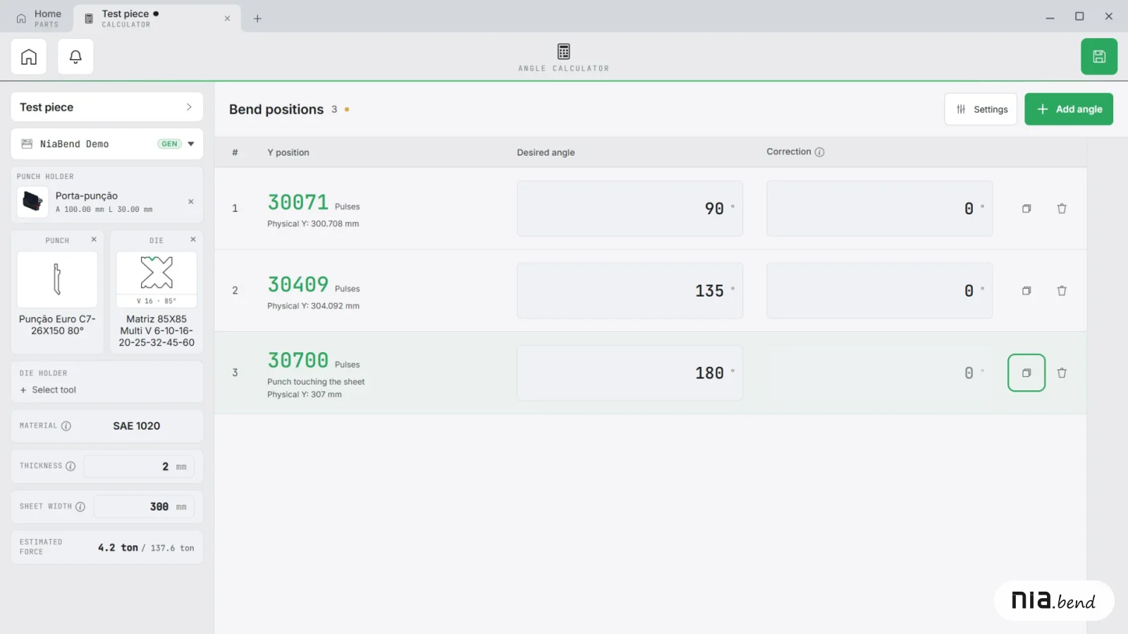
In NiaBend, this calculation lives in the Angle Calculator. You choose the machine, the punch, the die and its V opening, the material, the thickness and the sheet width, then type in the angles. For each one, the calculator returns the Y axis position, using the same bending law as that machine's simulation. Since it doesn't need a drawing, it works for one-off bends and test strips.
Figure 1 shows an example with 90°, 135° and 180°; at 180°, the punch only touches the sheet, so the value is the touch position. When the estimated force exceeds the machine's tonnage, the rows lose their Y value and a warning explains why.
Millimeters or readout pulses
So that the number matches the readout, the NC machine is set up with the Generic (panel adjustment) controller, and each axis gets a virtual zero. It stores the readout unit, the counting direction and two readings taken without moving the axis: the panel reading and the actual measured position. From then on, the calculator, the simulation and the report show the value to set on the panel.
Angle correction on the first part
Even with the calculation, the first part can come out open or closed. You measure the angle and enter a correction on that angle's row: a positive value opens the bend, and a negative value closes it. The number is the total correction relative to the requested angle, and Y is recalculated right away.
For example, you asked for 90° and the part came out at 91.5°: the correction is 90 − 91.5 = −1.5. On the next part, already at −1.5, the measured angle was 90.4°, and the new correction is −1.5 + (90 − 90.4) = −1.9.
If your control can be programmed by angle, key in the Y value, not the angle. When you program the angle, the control redoes the calculation with its own tables and the correction is lost.
Bend sequence on the Auxiliary Panel
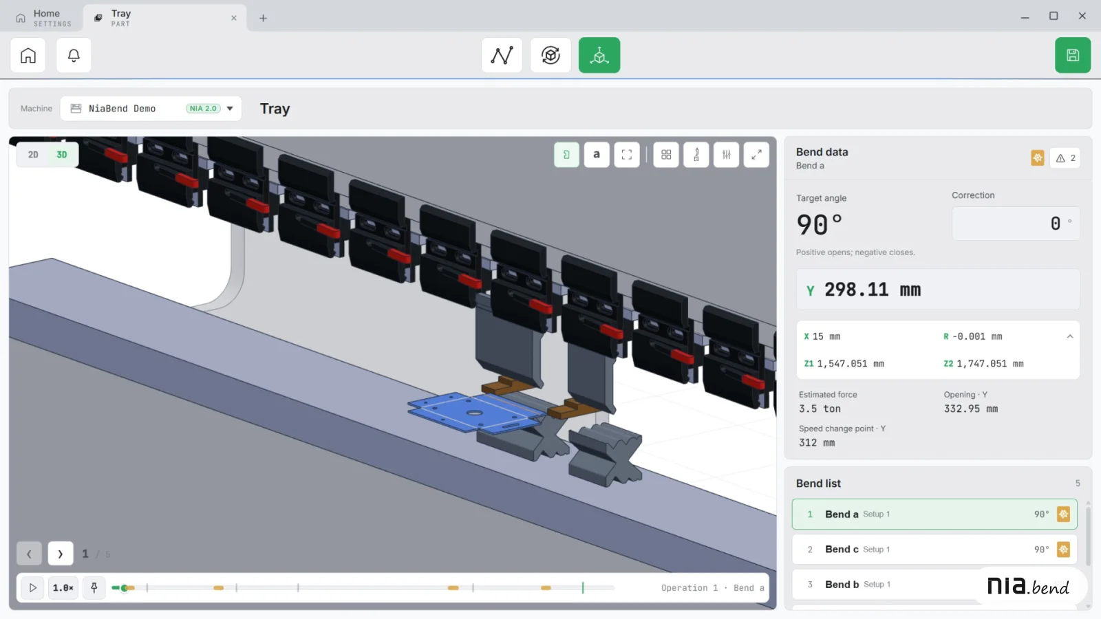
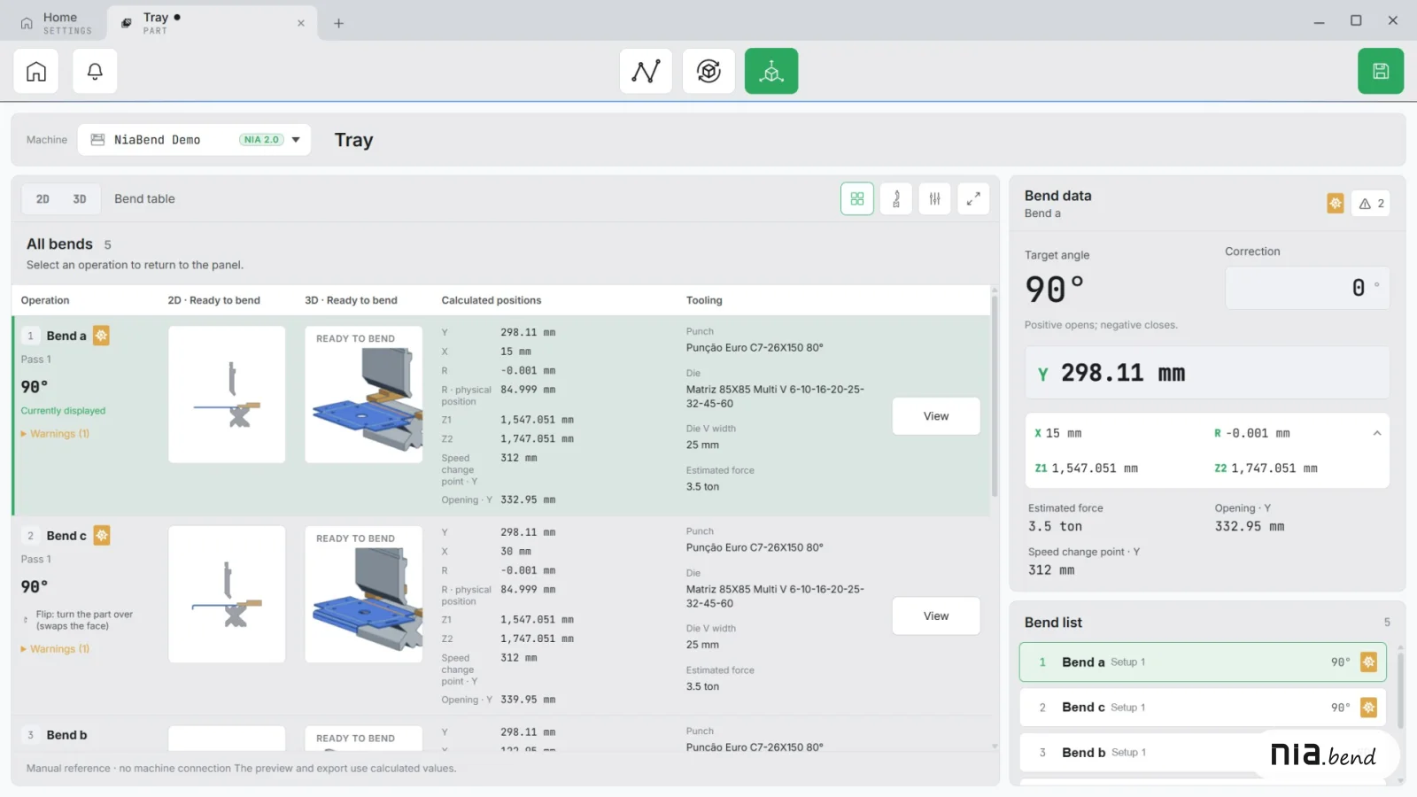
In NiaBend, the part, drawn or imported, is simulated for your NC press brake, and the simulation sets the bend order, the tooling and the position of every axis. Next to the machine, the Auxiliary Panel shows that simulation one bend at a time, as Figure 2 and Figure 3 show:
- the bend animation, in 2D or 3D;
- the Y, X and R positions, the way your readout shows them;
- the tooling arrangement and the drawings attached to the part;
- the correction for each bend, saved for that machine.
Video 1 shows this path on an NC press brake. If there is no computer at the machine, the PDF or HTML report carries the same positions, bend by bend.
Bend calibration
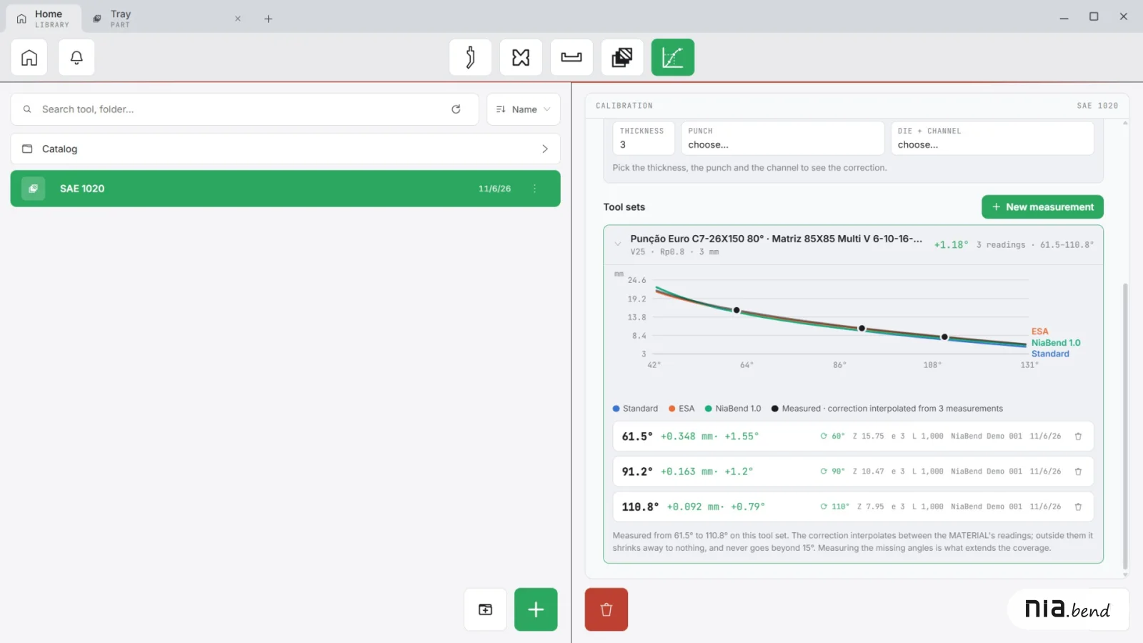
Calibration covers what no formula can see, such as play in the machine and tooling wear. It uses test strips bent at several angles, with the Y readout and the measured angle recorded for each one.
NiaBend's angle calibrator stores that difference by material and tooling, as in the chart in Figure 4. The calculator and the panel can then apply it to the bends that follow.
Software or control retrofit?
| Aspect | Calculation and simulation software | CNC retrofit |
|---|---|---|
| What changes | The calculation, the sequence and the positions reach the operator | The control, the sensors and the axis drives |
| Who positions the axes | The operator | The control |
| Machine downtime | Only to measure the axis references | During installation and tuning |
| What it needs from the machine | That it repeats the position the readout shows | A frame, guides and hydraulics fit for the new control |
Software is the better fit when the machine is mechanically sound and the time goes into dialing in:
- many different parts in small batches;
- first parts that take several tries;
- NC and CNC press brakes in the same shop, with every part prepared the same way.
A retrofit is the better fit when the bottleneck is the axis motion itself:
- many bends per part in large batches, where every manual adjustment adds to the cycle;
- machines that need to control both cylinders and compensate for deflection on their own.
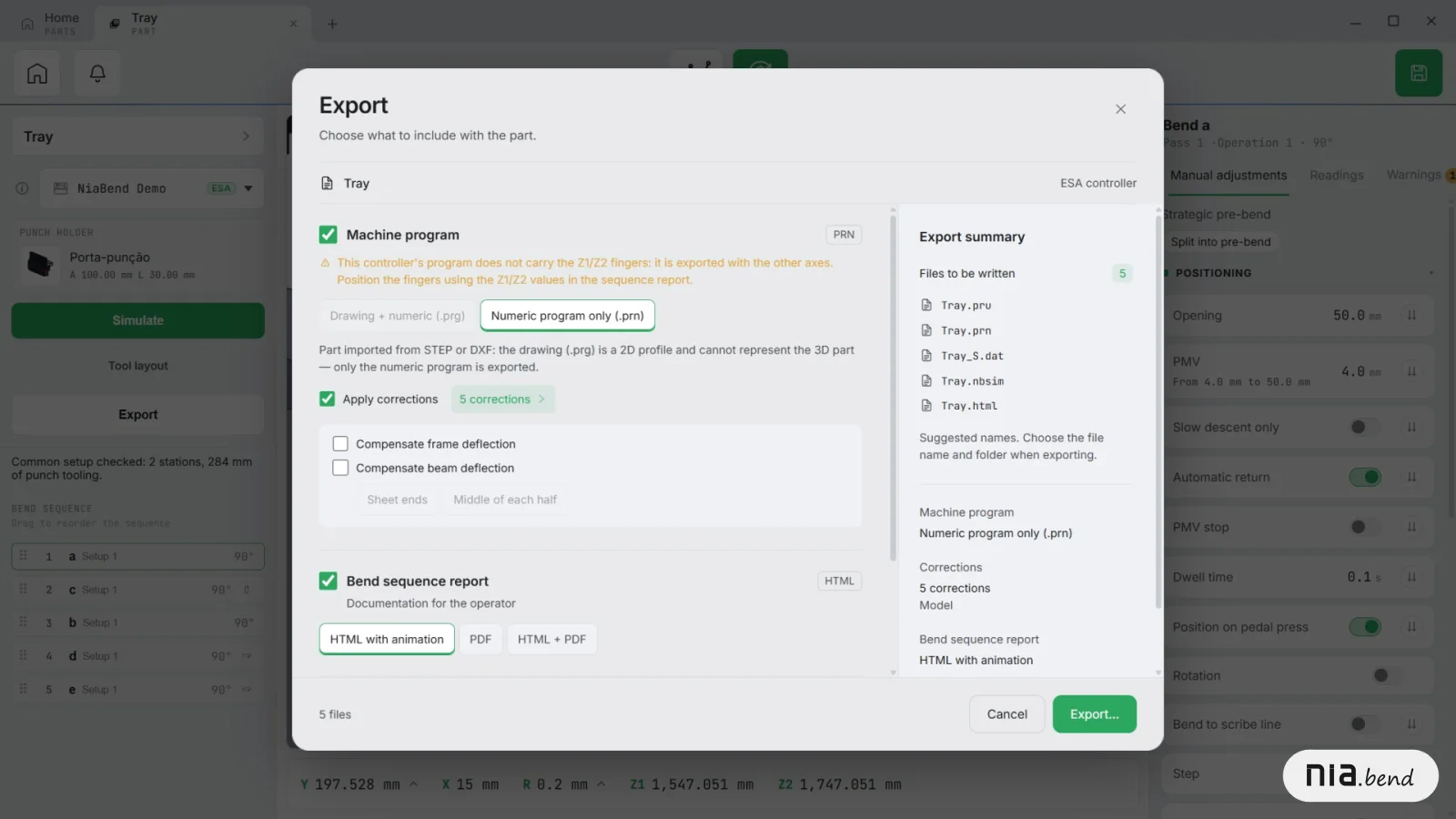
If the hydraulics or the electrical cabinet already need an overhaul, or the guarding has to be brought up to current safety standards, it pays to use the same shutdown. The two paths are not mutually exclusive either: your parts, tooling and machine setups keep working after a retrofit. NiaBend exports ready-to-run programs for some CNC controls, as in Figure 5 and Video 2.
Where to start
- Set up the machine as it really is, with the readout reference for each axis.
- Enter the tooling you actually own, with measured working heights.
- Use the calculator on everyday bends and compare it with the operator's notebook.
- Measure and correct; where the same error keeps coming back, calibrate.
- Move on to complete parts in the Auxiliary Panel.
Frequently asked questions
Does NiaBend move the axes on my NC press brake?
No. It calculates and displays the positions, with no communication with the control or the PLC. The operator sets the Y axis and the backgauge, and the first part of every new program is still checked bend by bend.
My readout shows pulses, not millimeters. Will it work?
Yes. In the axis's virtual zero, choose pulses and enter how many millimeters each pulse is worth and where the readout puts the decimal point.
Conclusion
Turning an NC press brake into a CNC can start with the calculation. If the machine is mechanically sound and the time goes into dialing in the first part, start with the Angle Calculator and the Auxiliary Panel. If the bottleneck is axis motion in large batches, consider a control retrofit.
The article on the benefits of press brake simulation covers what simulation changes in the rest of production. To try it on one of your own parts, the free NiaBend demo lets you draw and simulate the bend on your computer.