Pre-bend vs. process bend: what is the difference?
In this article, we explain the difference between a pre-bend and a process bend, when each move clears a collision on the press brake and how to check the result in simulation.
Pre-bends and process bends are two moves that clear collisions on the press brake when no bend sequence works. On those parts, whatever the order, a flange that's already bent hits the punch, the die or the machine.
Before you change the design, try one of them. Below, we explain the difference between the two, using the terms as NiaBend does, and how to check the result in the simulation.
Pre-bend vs. process bend: the difference
The difference is in what stays in the finished part. With a pre-bend, the bend is in the drawing and is simply made in two steps. With a process bend, the bend is not in the drawing: it's created for manufacturing and undone later.
| Item | Pre-bend | Process bend |
|---|---|---|
| In the finished part? | Yes | No, it's undone at the end |
| Where it goes | On a bend in the drawing | In the middle of a flange |
| Steps | a1, to an intermediate angle, and a2, the finish | P1, to an angle α, and P2, back to 180° |
| Extra operations | One, because the bend is made in two | Two, and the unbent zone usually leaves a mark |
| When to use it | Hems, or a bend that has to be halfway done when another one is made | When no combination of the drawing's bends clears the way |
| How to create it in NiaBend | Split into pre-bend, in the step inspector; for hems, it comes from the drawing | Process bend, in the sequence list |
| Changes the flat pattern? | No | No |
Angles here are included angles, measured between the flanges: 180° is a flat sheet.
Pre-bend: the same bend in two steps
A pre-bend takes a bend only to an intermediate angle and leaves the finish for later. The finished part is the same; only the path changes. It shows up in two situations: when another bend has to get through, and in hemming.
When another bend has to get through
Picture a bend c that hits the flange of bend a. With a still flat, the flange hits in one place; with a fully formed, it hits somewhere else. With a at an intermediate angle, c clears.
The way out is to split a into two steps: a1, to the intermediate angle, before c; and a2, to the drawing angle, after c. NiaBend calls this a strategic pre-bend. In Figure 1, a1 stops at 135° and a2 does the finish.
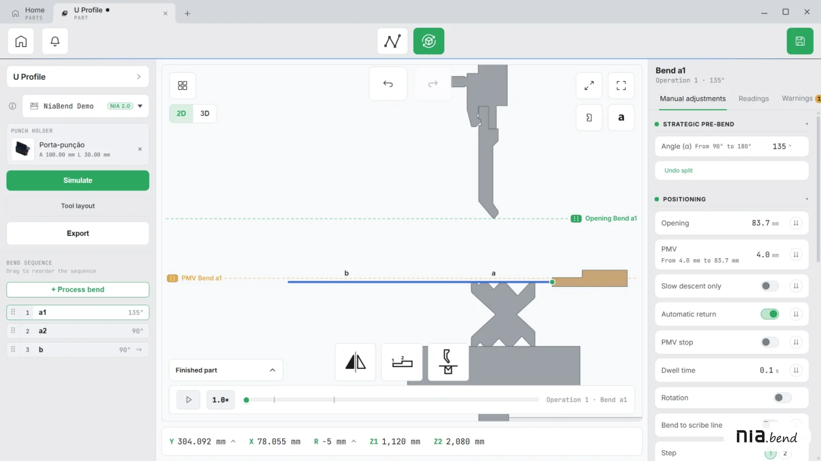
How to split a bend in NiaBend
- Select the bend's step and click Split into pre-bend in the step inspector. The program creates a1 and a2, the Bend finishing, each on its own row in the sequence.
- Set the Angle (α) of a1 within the accepted range written with the field: from the drawing angle to 180°.
- Drag a2 to after the bend that has to get through. The program won't accept a2 above a1.
- If the move doesn't work, Undo split goes back to a single bend.
Video 1 shows the whole move.
Hemming, the classic case
A hem is a flange folded back onto the sheet, to stiffen the edge and get rid of the sharp cut edge. It doesn't come from a single bend: first an acute pre-bend, with an acute punch and die, then the flattening step, where the flange is pressed down against the sheet.
In the NiaBend drawing, a bend with an angle below 1° becomes a hem and gets its own fields. The Pre-bend field shows the allowed range and a suggested value. If the tooling can't reach the acute angle needed, the field locks and points you to an acute hemming punch.
That pre-bend only enters the feasibility check and doesn't change the geometry or the flat pattern. In the sequence, pre-bend and flattening are two rows that can be separated. During flattening, the part lies flat and the die locates it, with no backgauge move.
Process bend: a temporary bend
A process bend is a bend that only exists during manufacturing. It goes in the middle of a flange, is bent to an angle α and, further down the sequence, is unbent until the sheet is flat again. While it exists, it changes the part's shape: a stretch of flange that would hit while straight may clear while tilted.
It solves what the bend order and the pre-bend can't: when no combination of the drawing's bends, flat, halfway or finished, clears the way. In Figure 2, P1 bends the flange to 150° and P2 takes it back to 180°, leaving the sheet flat at the end.
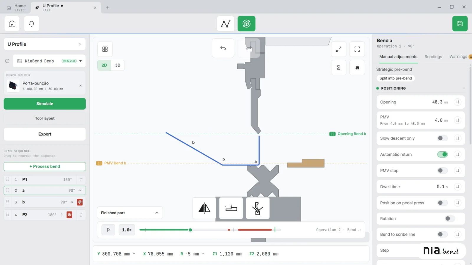
How to insert a process bend in NiaBend
- In the sequence list, click Process bend.
- In the window, click the flange on the drawing of the finished part, which shows the letter of each bend.
- Set the Angle (α), the Position along flange and the Direction. The position snaps to the middle of the flange, where support for the unbend is firmest.
- Place the bend (P1) and unbend (P2) steps in the sequence.
In Video 2, note that P1's direction and angle avoid the collision.
Process bend rules and cost
- The sequence search doesn't place process bends.
- There's one process bend per section, and short flanges are refused.
- The step is left out of the force check, because the air bending formula doesn't describe unbending.
- On the unbend, the backgauge stops the part and the X axis retracts as it opens up. If support gets unstable, the warning suggests centering the bend or using a narrower die.
- The bent-and-flattened zone usually leaves a mark: on a cosmetic face or a tight-tolerance part, check with engineering.
How to check the move in the simulation
In the NiaBend simulation, you can test both moves before cutting any sheet, with this routine:
- Run Simulate. If no order works, the program says it found no collision-free sequence and shows the least severe one.
- Find where it hits. The sequence list flags the step with Collision or Possible collision, the animation timeline shows red and amber marks, and the Warnings tab tells you what hit. Selecting the step jumps the view to the moment before the ram comes down, in 2D or 3D.
- Apply the move: split the bend into a pre-bend or insert the process bend, and place the steps.
- Wait for the check, which runs step by step. While a row shows Checking collisions…, the absence of a collision flag isn't approval yet.
- Play the whole sequence and open the Sequence overview, with one thumbnail per operation.
If the attempt doesn't work, the simulation's Ctrl+Z undoes it: its history covers the sequence order, the manual adjustments and the process bends. Before export, NiaBend completes the collision check, so the program and the report describe the same simulation.
Since the simulation works with what you entered, the first part still gets checked on the machine. What else the simulation checks at each step is covered in press brake simulation benefits.
Frequently asked questions
Do pre-bends and process bends change the flat pattern?
Not in NiaBend. The strategic pre-bend and the process bend are sequence decisions made in the simulation, and the flat pattern comes from the part drawing. The hem's pre-bend doesn't change the geometry or the flat pattern either.
When is it better to change the tooling or the design?
When the mark left by the unbent zone isn't acceptable, or when two extra operations weigh on the batch. Before the move, try other tooling: a gooseneck punch, for example, makes room for return flanges. If nothing clears, it's a conversation with engineering.
Does every press brake support these moves?
It depends on the control. The machine setup declares whether the controller offers strategic pre-bend and process bend. When it doesn't, the move is left out on that machine, with a warning. Nothing is deleted from the part, and on a compatible machine it comes back.
Conclusion
Pre-bends and process bends solve the same problem, a collision, from different directions. If the bend exists in the drawing and just needs to happen at another moment, split it into a pre-bend. If the part only clears with a temporary shape, use a process bend and accept the two extra operations and the possible mark on the sheet.
Either way, decide in the simulation, with the real machine and tooling entered, not on the first cut blank. To try the NiaBend simulation, download the free demo.