Bending simulation for quoting: why use it?
In this article, we explain how bending simulation helps you quote formed parts: whether the part bends, with which tooling, in how many setups, how long it takes and what the flat pattern is.
Bending simulation for quoting shows, before the price is set, whether the shop can bend the part and what will drive its cost. Without it, the price comes from the print. Only on the shop floor does someone find out that the flange is too short for the V die, that the third bend hits the ram or that the part needs a tool the shop lacks.
At that point, every way out is expensive: a special tool, a remade part, a missed due date or an awkward call to the customer. Below, we explain what the simulation answers while the design can still change.
Bending simulation for quoting: what it answers
A bending simulator builds the part's bend sequence on the machine and tooling on file. At the quoting stage, it answers five questions:
- Can the part be bent with the shop's machines and tooling?
- With which punch and die, and in how many setups?
- How long do the part and the batch take?
- What flat pattern goes to cutting?
- What should change in the design before the order?
Orders in STEP or DXF
When the order arrives as a 3D model, the STEP file imported into NiaBend becomes a sheet metal part: every bend is recognized with its angle, direction and radius, and the part is flattened on the spot (Figure 1).
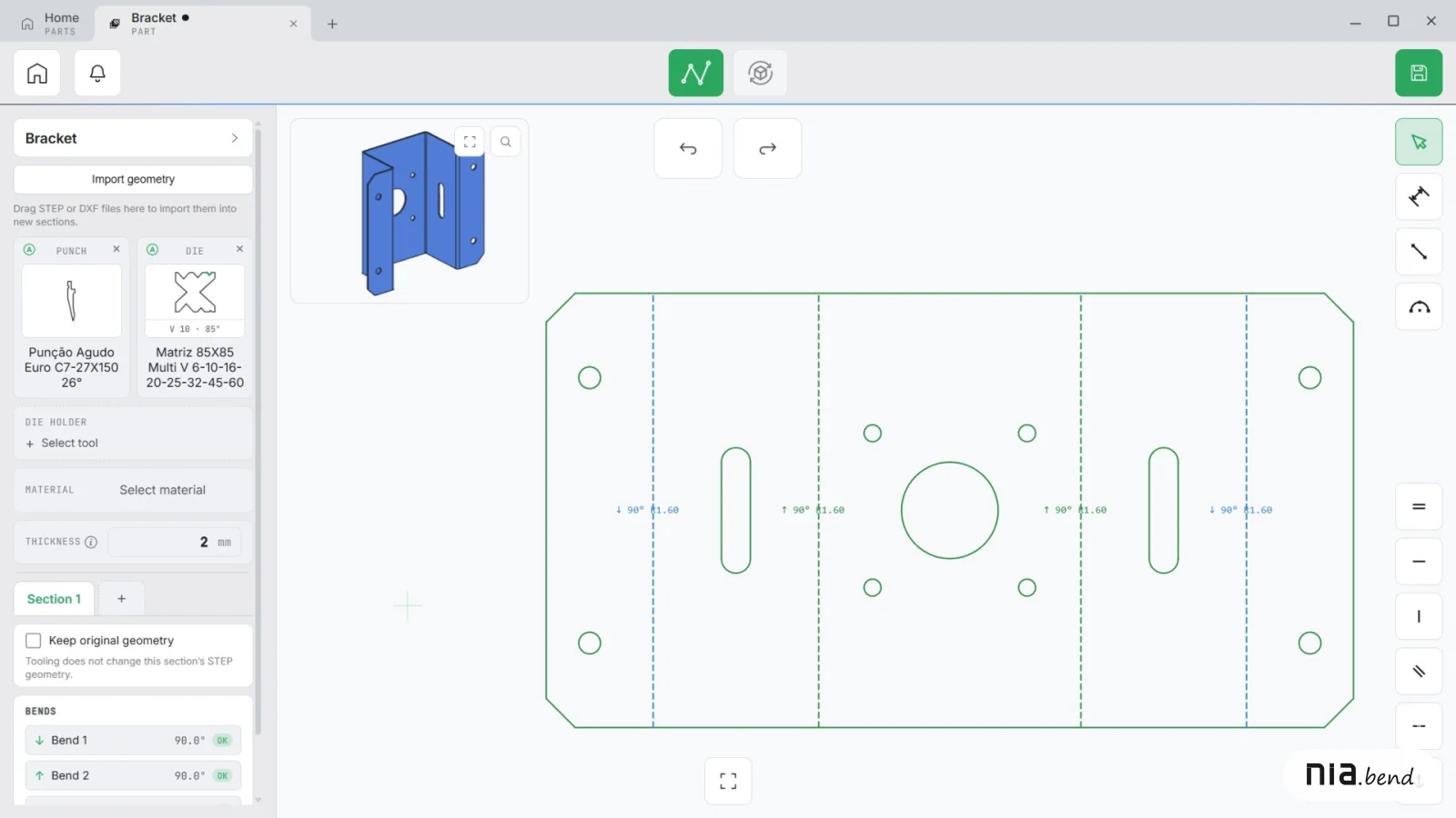
The detail that matters for the quote is the radius. The designer picked one in the model, but in air bending the inside radius (Ri) is whatever the die and the material produce. NiaBend adapts the part to your tooling's inside radius and keeps the outside dimensions, without changing the cutouts in the file.
Where the cutouts can't take that radius, the 3D part marks the bend as not feasible in amber and the spot where the sheet tears or deforms in red. The message tells you what radius range the geometry accepts, and a window shows the original STEP and the adapted part side by side. Video 1 shows the path from the STEP file to the exported program.
If the order comes as a DXF, be careful: it carries neither thickness nor angles. Bends come in at 90° and have to be checked against the print.
Feasibility: can the part be bent?
The print alone doesn't tell you if the shop can make the part with its machines and tooling. In the simulation, every bend gets a verdict before the sequence:
- angle not compatible with the tooling;
- flange too short for the die opening;
- force over the tool's capacity.
A machine the part doesn't fit in is grayed out, with its bending length shown. Then the sequence search checks collisions and axis travel on the chosen machine, as we explain in press brake simulation benefits.
Two answers need a careful read:
- No setup is possible for a bend on that machine. That's proof: not even a punch and die dedicated to that bend will make it.
- The search hit its time limit without a clean setup. That doesn't prove the part is impossible. Look closely before turning down the order.
Setups and tooling: what drives cost
Two parts with the same number of bends can cost very different amounts, depending on machine setups and part handling.
The sequence shows every operation. When one setup can't handle the whole part, the work can be split into Setup 1 and Setup 2, and every changeover is machine downtime that belongs in the price. Steps where the part is rotated or flipped also count toward the time.
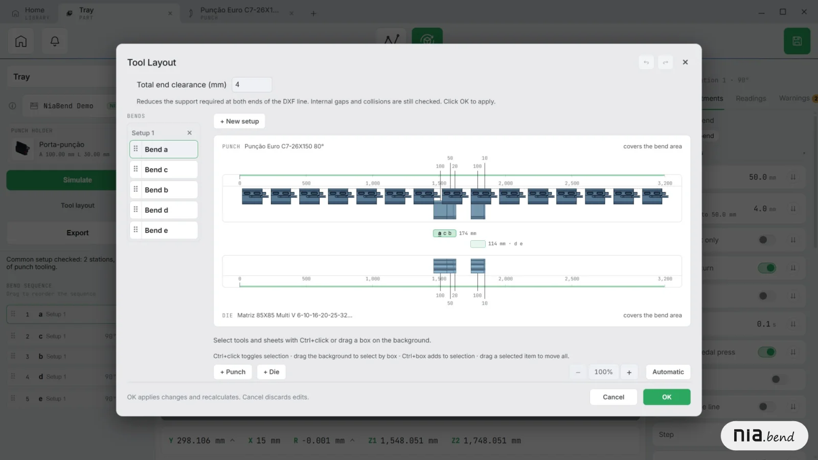
The Tool layout shows the punch and die sections from stock and the stations, with the letters of the bends each one makes (Figure 2). With section stock in the tooling library, a tool too short for the bend is flagged with how much is missing.
Die selection and force
In die selection, the window shows what the part needs: the ideal die opening, 8 to 12 times the thickness, the shortest flange and the tightest bend. For 2 mm sheet, the ideal opening is between 16 and 24 mm. Whatever doesn't fit is grayed out, with the reason next to it.
Automatic tool selection picks the punch and die from the tooling on file. If nothing fits, and the library holds every tool the shop owns, the quote has two ways forward: budget for a special tool or propose a design change.
If a bend goes over the machine's tonnage, the options are a wider V, splitting the bend or moving the part to another press, and each one changes the cost.
Cycle time before the order
The cycle time the simulation estimates has two parts:
- Machine time: from the speed and travel of every move, such as ram descent, bending, return and backgauge travel.
- Operator time: from a production time table by part weight and size, multiplied by handling factors such as rotating, flipping and repositioning.
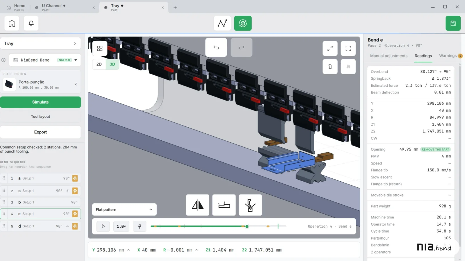
The Readings tab shows the estimated force, the axis positions and the times (Figure 3). In the figure, 20.1 s of machine time plus 14.7 s of operator time gives a 34.8 s cycle. Enter the quantity in Parts to produce and the time becomes the batch time, in hours and minutes, with a flag when the part needs two operators.
For that number to hold up in a quote, take three precautions:
- Tune the production time table to your shop, since it ships with reference values.
- Check the material density. Without it, the part has no weight, lands in the lightest bracket and the handling time comes out optimistic.
- Add setup changeover separately, since the estimate doesn't include it yet.
Flat pattern and cutting cost
Material and cutting cost depend on the flat pattern, the blank cut before bending. The developed length is calculated bend by bend, from the angle, thickness, inside radius and K-factor of each one.
The flat pattern comes out as a DXF, with the cut contour on one layer and the bend lines only marked, on layers of their own. Many parts can go out at once, each in its own file, so whoever quotes the laser cutting works from the same blank that will be bent.
A wrong K-factor makes the flat pattern too long or too short, as we explain in how the K-factor affects the flat pattern.
Report and feedback to the designer
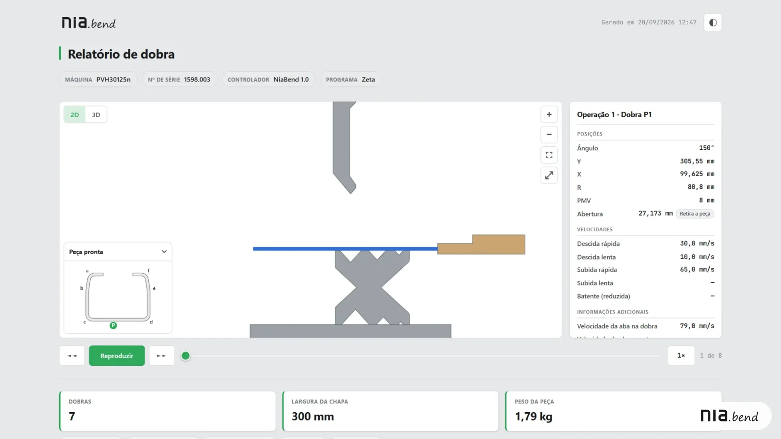
The time estimates go into the bend sequence report, with the developed length, weight, operations and setups. Exported as HTML, the report lists the steps, tools and positions (Figure 4). It opens in any browser and takes the animated sequence to the customer or the designer without them installing anything.
The best time to change a flange or a radius is before the order. After that, every change means a drawing revision, a new bill of materials and sometimes a new tool. With the simulation, the conversation with the designer gets specific:
- a flange too short for the die: lengthen the flange or use a smaller V;
- a model radius the tooling can't make: change the radius on the drawing or the tool;
- a corner with no relief that may tear at the tooling's radius: enlarge the relief before cutting;
- a bend that collides in every order: rework the geometry.
With the files on a server, the part simulated for the quote is the one production planning and the shop floor open after the order.
Frequently asked questions
Does the simulator calculate the part price?
No. It provides the data the price is built on: whether the part bends, with which tools, in how many setups, the estimated time, the weight and the flat pattern. Building the price is still the estimator's job.
Is the estimated time good enough for quoting?
It's a calculated estimate, not a measurement. It becomes reliable once the production time table is tuned to your shop and the material density is on file. Setup changeover isn't included.
Conclusion
Using bending simulation for quoting doesn't mean simulating everything. Start with the parts that bring the most surprises: short flanges, many bends, STEP files with tight radii and new materials.
If the part bends, use the simulation's time, setups and flat pattern in the price. If the simulation points to a problem, take the flange, radius or relief to the designer before the order. To try the software, download the free NiaBend demo.